


 English
 Français
 Español
 Deutsch


Home · News · Industry News · How to Reduce Defects in Automotive Interior Injection Molding: A Practical Guide
Industry News
How to Reduce Defects in Automotive Interior Injection Molding: A Practical Guide
2026-09-09Table of Contents
- 1 The Cost of Defects in Automotive Interior Injection Molding
- 2 Common Defect Types and Their Mechanisms
- 3 Part Design: Remove Defects Before Cutting Steel
- 4 Material Control: Moisture, Temperature, and Consistency
- 5 Mold Design: Where the Steel Decides
- 6 Process Tuning: The Last Line of Defense
- 7 Inspection: Closing the Loop
- 8 Conclusion: A Systematic Approach to Lower Defect Rates
The Cost of Defects in Automotive Interior Injection Molding
A textured interior trim panel that shows a weld line on its high-gloss edge is not an accident. It is the downstream result of part geometry, gate placement, material condition, and process settings locked in before the first test shot. Once a defect becomes visible on a production part, the root cause was usually decided earlier in the chain.
Interior parts are among the most demanding injection molded products. They sit within arm's reach, so the eye catches gloss variation, sink marks, and witness lines. They also carry functional responsibilities: airbag covers must tear along a predictable line, vents must rotate smoothly, and clips must survive assembly. A defect that escapes the plant means rework, scrap, PPAP delays, or rejected shipments at the customer's dock.
Reducing defects is therefore a sequence of decisions across part design, material control, mold design, process tuning, and inspection. Each stage is covered below.
Common Defect Types and Their Mechanisms
Each defect has a fingerprint. Recognizing the mechanism tells you which stage of the chain to change.
| Defect | Typical mechanism | Where it appears |
|---|---|---|
| Sink mark | A local thick section shrinks more than the surrounding skin, pulling the surface inward | Above ribs, bosses, and thick junctions |
| Weld line | Two melt fronts meet without fully bonding | Around holes, inserts, or where flow divides |
| Flow mark / tiger stripe | Unstable flow front creates alternating glossy and matte bands | Large flat panels, long flow lengths |
| Short shot | Melt freezes before reaching the end of the cavity | Thin ribs, remote edges, deep texture |
| Warpage | Differential shrinkage from non-uniform cooling or material orientation | Flat panels, frames, carriers |
| Flash | Cavity pressure overcomes clamp force or escapes through gaps | Parting line, ejector pin locations |
Every defect can be attacked from several directions. A weld line can be shifted by gate position, strengthened by higher melt temperature, or hidden by surface texture. The right action depends on where the part is in its development cycle.
Part Design: Remove Defects Before Cutting Steel
The cheapest place to prevent a defect is the CAD model. A change on screen costs nothing; a change in hardened steel costs time and money.
Wall Thickness Planning
Keep the nominal wall thickness as uniform as possible. For interior structural panels, 2.5 to 3.0 mm is a common target, but the exact value depends on material and part length. Avoid local thick sections: every extra millimeter of thickness lengthens cooling time and raises sink mark risk on the visible surface.
When a thickness change is unavoidable, make it gradual. A maximum transition ratio of 1 to 1.5 between adjacent sections limits differential shrinkage and prevents waviness and internal stress.
Ribs, Bosses, and Draft Angles
Ribs are the most frequent source of sink marks on interior parts. Keep the rib base at 50 to 60 percent of the nominal wall thickness to protect the opposite class-A surface. For a 2.8 mm ABS or PC/ABS panel, a rib base of around 1.5 mm is usually safe. The same logic applies to bosses: keep the wall under the boss thin, or core it out.
Draft angles deserve attention because most interior parts carry a leather grain or fine texture. Texture increases friction against the mold wall, so a deeply grained part may need 2 to 3 degrees of draft per side instead of the 1 degree used on smooth surfaces. Insufficient draft leads to scratched texture during ejection.
Add a radius of at least 0.3 to 0.5 mm at rib bases and internal corners. Sharp corners act as stress risers and reduce the crack resistance of snap-fits and airbag tear lines.
For a deeper discussion of design review and material selection for interior applications, our automotive interior mold design principles and material selection guide covers the logic from part specification to tooling concept.
Material Control: Moisture, Temperature, and Consistency
Material condition influences final surface quality more than most process settings.
Common interior materials include PP for door panels and trim carriers, ABS for trim parts, PC/ABS for structural components and airbag covers, and PA6 where heat resistance is required. Each has a defined processing window, and all behave differently when pellet condition changes.
Moisture is the most common hidden cause of surface defects. ABS and PC/ABS are hygroscopic; in humid conditions they absorb enough water within minutes to form silver streaks and splay. Dry the material to a dew point below -30°C for two to four hours at 80 to 100°C, and start production only when moisture content is below the supplier's recommended limit.
Regrind is a second control point. Scrap must be kept clean and blended in a consistent ratio. Variation in the regrind ratio changes melt flow rate from batch to batch, which shows up as flow marks or gloss variation on interior surfaces.
Mold Design: Where the Steel Decides
Once the part design is frozen, the mold is the second line of defense. It fixes the flow path, the cooling, the venting, and the appearance of every surface.
Gate Position and Balanced Filling
Gate position is the first design freedom that matters. Position gates on hidden surfaces where possible, and steer the flow so weld lines land in low-visibility zones. Longer parts such as instrument panel carriers often need multiple gates; the runner system must then be balanced so all flow fronts meet at the same time and pressure. An unbalanced runner causes overpacking in one region and short shots or voids in another.
Venting
Venting is easy to overlook and difficult to correct later. Channels 0.02 to 0.03 mm deep at the parting line and along ejector pins let air and volatiles escape as the melt advances. Without them, compressed air can burn the surface, create blush, or prevent full filling. Deep textures need generous venting because air is trapped in the texture valleys.
Cooling and Surface Finish
Non-uniform cooling is a leading cause of warpage. Cooling channels should follow the part geometry, typically 20 to 30 mm apart, and the mold temperature difference across the part should stay within roughly 5°C. Conformal cooling, where the channel matches the part contour, is increasingly used on interior parts with complex curves.
Surface finish must be specified without ambiguity. A mirror-polished surface exposes small defects, while consistent texture hides minor sink and flow lines. Changing the texture after the first trial requires reworking the steel, so agree the class-A grade up front.
Experienced toolmakers translate these requirements into reliable steel. An instrument panel frame injection mold, for instance, combines a long flat panel, tight tolerances around the airbag opening, and a surface that matches the surrounding trim. The mold design review is where those risks are either removed or accepted.
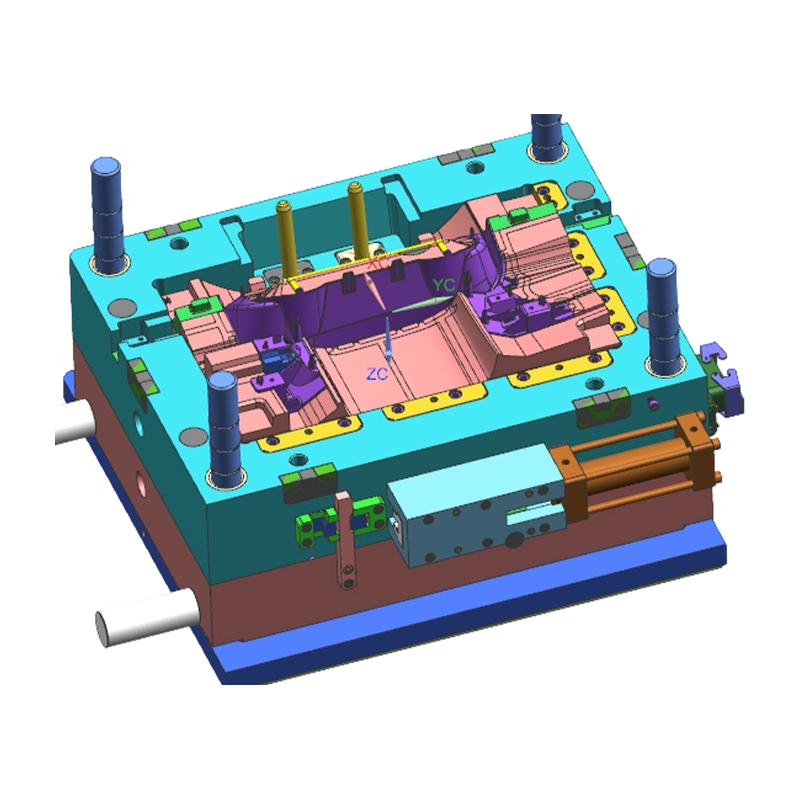 Wholesale Instrument Panel Frame Injection Mold Suppliers, Company, ExporterFanze T&M (Jiashan) Co., Ltd. Is China Wholesale Instrument Panel Frame Injection Mold Suppliers, Company, Exporter, This product line sp...View Product →
For a broader overview of tooling for different interior components, our automotive interior plastic parts injection molds category covers vents, airbag housings, trim panels, and storage systems.
Process Tuning: The Last Line of Defense
The best mold still produces defects if the process is not developed and controlled carefully.
Use a staged injection speed profile rather than a single fill speed. A slow first stage prevents hesitation at the gate, a fast middle stage fills thin ribs before the melt cools, and a final deceleration before the cavity is full avoids pressure peaks and flash.
Packing pressure compensates volumetric shrinkage. Sink marks above ribs and bosses are corrected during packing, but only if the pressure is sufficient and held until the gate freezes. Excessive packing creates residual stress that later appears as stress whitening on textured surfaces or cracks at snap-fits.
Mold temperature affects gloss, flow, and warpage at the same time. A PP interior panel commonly runs at 40 to 60°C, while a textured PC/ABS part may need 60 to 80°C to reproduce the grain reliably. The best setpoints come from a short Design of Experiments that varies melt temperature, injection speed, packing pressure, and mold temperature against the appearance and dimensional requirements.
Production environment matters too. Humidity affects drying time between storage and hopper, and insufficient barrel purging between color changes leaves streaks on light-colored parts.
Complex components stress all of these variables at once. An automotive air conditioning vent plastic parts injection mold, with thin-walled louvers and tight interfaces to the dashboard, forces the process developer to balance filling, packing, and cooling simultaneously.
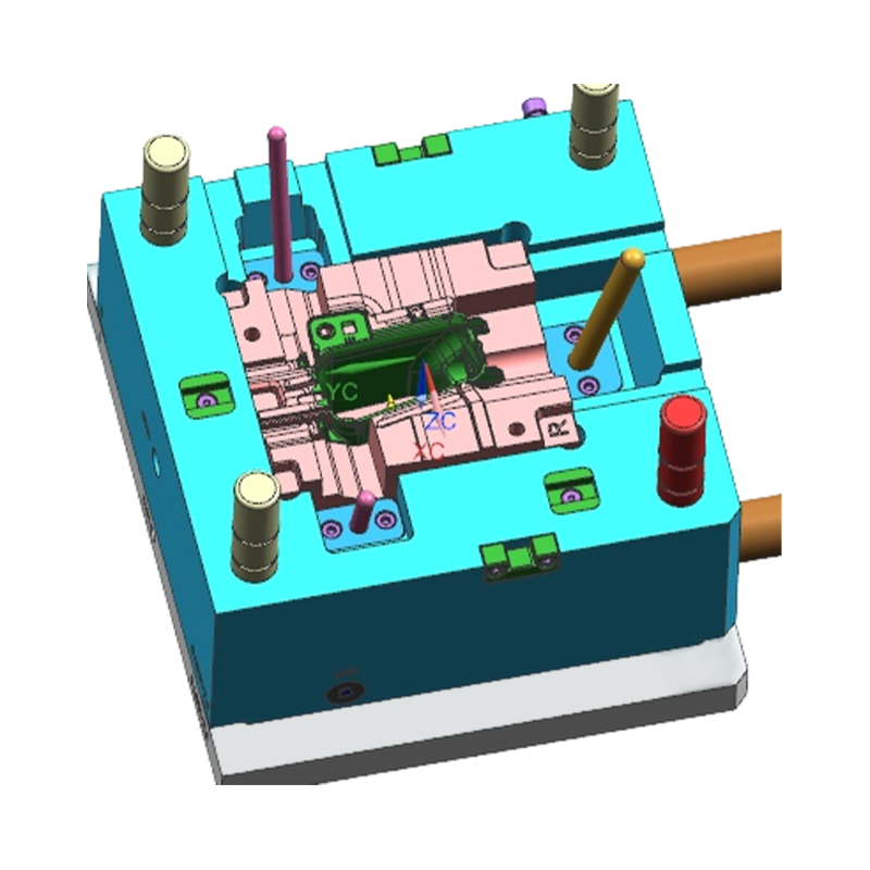 Wholesale Automotive Air Conditioning Vent Plastic Parts Injection Mold SupplierFanze T&M (Jiashan) Co., Ltd. Is China Wholesale Automotive Air Conditioning Vent Plastic Parts Injection Mold Suppliers, Company, Export...View Product →
Inspection: Closing the Loop
Inspection alone does not reduce defects, but it tells you whether your countermeasures work.
Visual inspection should be performed under standardized light. A part can look fine in daylight and fail under showroom lamps, so lighting conditions and reference plaques for texture and gloss must be agreed before series production.
Focus dimensional inspection on features that cause assembly problems: clip slots, gaps and flushness at panel interfaces, and airbag tear line thickness. Calculate Cpk for these features and act when it falls below 1.33, especially where safety is involved.
Monitor the process with SPC on melt temperature, injection pressure, and cycle time to catch drift before a bad part is made. A stable, documented process running under IATF 16949 practices produces far lower defect rates than one where each shift tunes by feel.
Conclusion: A Systematic Approach to Lower Defect Rates
Reducing defects is a sequence of connected decisions, not a single fix. Part design must respect wall thickness and draft, material handling must control moisture and regrind consistency, mold design must balance filling, cooling, and venting, and the process must be developed with data. Miss one link and the others cannot fully compensate.
The economics justify the effort. A panel with a 5 percent defect rate at a unit cost of ten dollars creates five thousand dollars of waste per ten thousand parts, before counting rework labor and the risk of stopping the customer's assembly line.
Bringing the tooling and molding partner in early shortens the learning curve. Fanze T&M has combined mold development and injection molding since 2005, supplying the automotive supply chain with solutions such as the driver airbag housing cover injection mold, where melt flow around the tear line decides both appearance and safety.
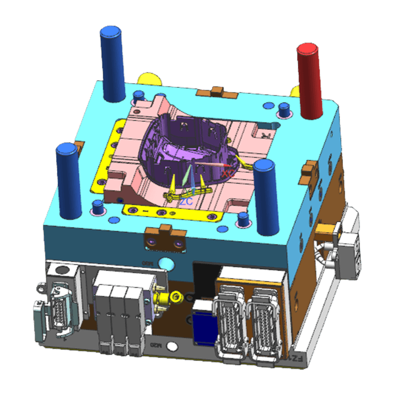 Wholesale Driver Airbag Housing / Cover injection mold Suppliers, Company, ExporFanze T&M (Jiashan) Co., Ltd. Is China Wholesale Driver Airbag Housing / Cover injection mold Suppliers, Company, Exporter, This product ...View Product →
If you are evaluating suppliers, the overview of choosing an injection molder for dashboard components lists the practical criteria for reviewing process capability, quality systems, and project experience before metal is cut.
Categories
- Company News(2)
- Industry News(32)
Product Category
-
Printer Components & Parts
-
Two-color Plastic component & tool
-
Plastic Multi-way Connectors
-
Threaded Plastic injection molded part
-
Home Appliance Injection Parts
-
Robot shell injection mold
-
High-Gloss Transparent PC injection mold
-
Motorcycle Fairings & Bodywork plastic injection mold
-
EV Charging pile plastic injection mold
-
Automobile wire harness
-
Automotive interior plastic parts injection mold
Related Tag
-
Automotive Interior Plastic Components Injection Mold
Automotive Interior Injection Mold
Automotive Interior Trim Plastic Parts Injection Mold
Automotive Door Panel Plastic Parts Injection Mold
Automotive Dashboard Injection Mold
Automotive Dashboard Plastic Parts Injection Mold
Automotive Air Vent Plastic Parts Injection Mold
Automotive Instrument Panel Plastic Parts Injection Mold
Automotive Center Console Plastic Parts Injection Mold
High Precision Automotive Interior Plastic Parts Injection Mold

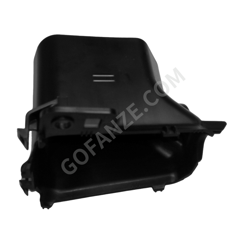

- Automotive interior plastic parts injection mold
- Automobile wire harness
- EV Charging pile plastic injection mold
- Motorcycle Fairings & Bodywork plastic injection mold
- High-Gloss Transparent PC injection mold
- Robot shell injection mold
- Home Appliance Injection Parts
- Threaded Plastic injection molded part
- Plastic Multi-way Connectors
- Two-color Plastic component & tool
- Printer Components & Parts

